^
                                                                                            last SL2M3 Update , last Change 06/11/2020
Documentation
SL2M3: Postprocessor -> Isolation Milling
convert HPGL Export-Data from Sprint-Layout to Sequence Control Data for (CNC-Machines) Mach3.

For Files from Sprint-Layout 5 or earlier please use SL5toM3.


              for my lame English here Notes to the Text / Words:


Security Hight ist the Height
for Rapid Feed over the Copper

Revolutions means the Spindel Revolutions


Miller means the Milling Cutter
Driller means the Drill

Miller and Driller explanation:

The technology from SL2M3 is based
to differentiate between the tool Drill
and the drilling process.

As in the word drilling the term drill
is included, the term Driller is used
for the tool. The term Driller is not
in the word Drilling included.

The same goes for Milling and Miller.


The First Start When you 1st start will be prompted for the desired language. Possible: German (GR), English (US), French (FR) not complete, not tested.


Introduction
To the Isolationmilling and drilling of printed circuit boards I need only 5 Data. That's are:
File Name,
Security Hight Z,
Mill- / Drill- Depth Z,
possibly Feed,
possibly Revolutions.

The Program SL2M3 converts with this few Inputs and without much trouble quickly HPGL-/Excellon- Data from Sprint-Layout to G-Code for the Sequence Control to Mach3. (alsmost) All important Functions are combines in one Display.

It's that simple. No complicated set of tools more. No time-consuming check of lines and then determine the type of milling. No more tedious convert circles into holes. etc. etc.

Other features of SL2M3 that are made possible by the new milling-export of Sprint-Layout Version 6:
What else can SL2M3 yet? Not least, there is little support as the ...

!   An example of how SL2M3 generate the G-code from HPGL:  SL2M3-Demo.CNC


The Program


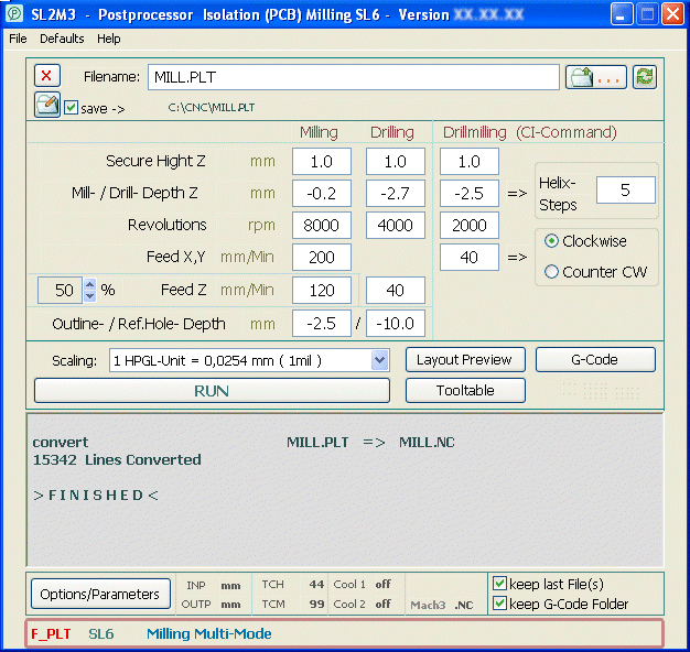
The Display from SL2M3
The program combines all the functions on one surface (Display). With Push-Buttons call in a separate window only the Options/Parameters and thegenerated G-Code. In addition, only generated from SL6 files the tool table and the layout preview.

The input fields below Drillmilling CI-Command are displayed only if this feature is used.
.


File Selection
The source files will selected with the extensions generated by Sprint-Layout (.PLT /.DRL) . For that opens the button [ . . . ] right to the File Name field in the familiar Windows File-Open. After opening the file causes SL2M3 a check of the file, recognizes the format and displays it in the status bar. If all conditions are satisfies, the conversion of the file by clicking the [ START ] will be set in motion.

Is under the file name [ ⎷ Save --> ] (=save here->) enabled, is the target file in the right shown folder (the same as the source file) saved.
The file name is the same as the name of the source file, the extender is in the box NC-File selected.

Is [ ⎷ Save --> ] (here) is not activated, the familiar Windows window Save as will Open to selection of folder and file name.

With the Folder-Button to the Left the folder to store G-Code and Tooltable can be permanently set.


Typed Measure:

Security Level Z & Mill-/Drill Depth Z
Here, the desired values are entered in mm. The input will be checked and the Comma Key converted to the decimal point required by the program. Thus, one can quickly enter the correct parameters with the number block and its comma key when typing. Also, the Enter key on the numeric keypad can used to switch into the next input field.
Possible entries:     -0.3     -.3     .3     0.3     3     3.0

Feed / Revolutions
Here, these values are entered without decimal. I want to have not the feed and/or the speed in the generated NC file (but set in Mach3), then I leave the input fields for these values empty (then there is a "?" in the inputfield). The Enter key can also be used here.
With the Up-/Down-Arrows in front of % Feed Z can be set that the Miller only when feed is input by the immers in Copper moved with the here reduced Feed

Reference Hole Depth / Outline Depth
Input Reference Hole Depth without Decimals. Outline Dept can input with Decimals. These two Inputfields are found on the bottom left of the status line and are slightly smaller.


Tool Table
[ ToolTable ] shows in SL6 files exported from the current tool table, as described in the CNC file is copied. ToolTable is underlined can be used for tools without diameter (eg Iso-Miller, Outline-Miller) left here entered the diameter of the table and thus *_tooltable.txt in the tool table (see Milling Export SL6) and transferred to the CNC file.


Scaling
With this selection, the size of the used HPGL unit can be determined. The correct size was 0,0254 mm (1 mil). Here most of the software probably 0,025 mm (1/40 mm) is used, so this selection. The decision coincides with Sprint-Layout from version 6 is already in the milling export, here there is also this selection*. The Sprint-Layout Version 5 before milling exports in Options > General Settings this must already be made: [ ⎷ HPGL scaling width 0.3937 instead of 0.4].

In SL2M3 the same level of Sprint-Layout as in milling export must be set by the user. There is currently no way this process of Sprint-Layout Export out to Automate. But, if within the export to the Filename 0254 or 0250 attached, SL2M3 recognizes and automatically adjusts (example: MILL0254.PLT).

* 1 HPGL-Unit 0,0250 mm (1/40 mm) = Faktor 0,4      /       1 HPGL-Unit 0,0254 mm (1 mil) = Faktor 0,3937


Automation:
1. Since (at least for me the Filename) is almost always the same parameters for isolation milling are used, these parameters are stored in an Ini-File as defaults and to the next start, reloaded. It's that simple.

2. SL2M3 can upload a milling File AND a drill File simultaneously. You can switch between the two by clicking the [ PLT< - >DRL ] left to the Start button. Both files should be in the same folder are, in this, the NC file is output.

SL5:
Among them is [ ⎷ PLT+DRL=NC ]. Sprint-Layout is the export of drilling data from Excellon format with the tool change. This allows the file to be merged when converting the milling and drilling file with a check at this point. The tool changes are applied to the control flow. The router then stops the tool changes to*, moves to tool change height and waits until START button is clicked again.

* I assume here that the user is familiar with SL2M3 of the tool length measurement in Mach3. To explain these methods here would go beyond the scope of this manual.

SL6:
In milling export files from Sprint-Layout Version 6 included "HPGL Drill Commands" (drilling and Reference Hole drilling) are converted into SL2M3 to real drilling cycles (G81 and G83), including tool change*. The function [ ⎷ PLT+DRL=NC ] is now obsolete and off.

* From SL6 also HPGL "tool change" (Select Pen) are the milling export the output to be interpreted by means of the tool allow SL2M3 and recognition from the job list in the conversion Drill Cycles.


Settings:
Some Settings* can be set used for the bottom bar over the the status line, also the keep last file(s) and keep G-Code Folder setting.

Is the [ ⎷ keep last File(s) ] activated, the last converted file will be displayed again by the next Start.

Ist [ ⎷ keep G-Code Folder ] activated, a file containing the paths of the source and the target file is saved for each source (PLT) file.


Options/Parameters:
With the [ Options/Parameters ] Button call the corresponding Dialog.

In the Options/Parameters dialog the tool change height and the maximum Z height can be set or Mach3-SafeZ* (G53 Z0) is selected for the tool change.
* Attention: SafeZ must be configured in Mach3!

on/off cooling 1 and cooling 2 (Mist/Flood) can be loaded into the G-Code.

The choice of extender for the Output-File (TXT, NC, CNC, NCC, TAP) is possible, but also G code for LinuxCNC (NGC) instead of Mach3.

For the diameter of Reference Hole Driller and Outline Milling Cutter standard values can be entered. If a value greater than Zero, it is automatically added to the Tool Table. The number of passes for contour milling in multiple Z infeeds can be selected.

If selected center punch holes in Sprint-Layout Export, the depth of the grain sizes can be adjusted here up to twice the depth.

Reference Hole drilling is performed with the G83 Drillcycle, retreat (parameter Q) every 3 mm. Changes are here possible.

Last but not least is the selection of Structured or cleared G-code, as also divide the G-Code into upper and lower PCB side (Split).
 
Structur
Clear
G00  Z 1.0
G83  X-2.489    Y 45.669  Z-10.0  R1.0  Q2.0   F33   
     X 109.169  Y 45.669
     X 109.169  Y-2.489
G00 Z1.0
G83 X-2.489 Y45.669 Z-10.0 R1.0 Q2.0 F33   
X109.169 Y45.669
X109.169 Y-2.489

Textured or Structured G-code is well suited for a visual inspection.Cleared G-code is, for example, imperative for further processing with Autoleveller*. Therefore the G-code can be splitted from SL2M3 in to the two levels, a separate export from Sprint-Layout is not necessary.
 
* Autoleveller is software that height differences of the circuit board on the router table balances (http://www.autoleveller.co.uk/).

if Laser exposure G-Code is activated, the code …_Laser.* is output without z-move. Instead, the Laser (with spindle function) switched according to Z-top / Z-bottom.
It can be selected graining Drilling holes, the function Center Punch in the Sprint Layout export is NOT necessary for this.
P adjusts the wait for the laser to turn on after positioning in ms (milliseconds), which is can be useful when switching through a Relay.
With drilling G-Code an additional File …_Drill.* with the drilling cycles is output, if drilling is selected in Sprint-Layout Export.

⎷ Only one Tool deactivate the Machine-Stops for Tool-Change.


Menu
The individual menu items on the File menu and the Help menu are self-explanatory.

- Defaults > delete:
   clears all input fields, so to speak, makes SL2M3 blank.

- Defaults > load:
   Represents the state of the input fields when starting SL2M3 restored. Useful if you have changed input fields for only one project.


Status Line
SL2M3 examines the file to edit as you open and with the data obtained, the status bar is equipped. Thus be-fore create the G-code all the necessary data are available and SL2M3 can make and display settings in the Status Line, also provide Errors and Hints in the Text Area.


StatusLine:
Typ     Status           Mode

Source-File   Hints
F-PLT   SL6   / SL6-Hx   Milling Multi-Mode
HPGL          -Hx = Helix-Fräsen (Drill-Milling CI-Command)
F-PLT           SL6-Hx   Drill-Milling
HPGL          -Hx = Helix-Fräsen (Drill-Milling CI-Command)
F-PLT   SL5+B / SL6+B    Milling Single-Mode
HPGL          SL5: With B-PLT and B-DRL is PLT+DRL=NC possible
B-DRL   SL5+F / SL6+F    Drilling
Excellon      SL5: With F-PLT is PLT+DRL=NC possible
B-PLT   SL5+F            Milling Mill-Mode
Excellon      SL5: With F-PLT is PLT+DRL=NC possible

The status indicators have the following meanings:

F-PLT   HPGL-File - Milling
B-DRL  Excellon-File - Drilling
B-PLT   HPGL-File - Drillinge (Name: BOHR*.PLT)

Hint: HPGL-Files from SL6 with Mill-Data AND with "DRIL" in the File-Name be (due to compatibility SL5) is interpreted as an error..

SL5...   File is in the format of Sprint-Layout to Version 5.
SL6...   File is in the format of Sprint-Layout from Version 6.

For example, an Excellon file from SL6 without decimal point has the same format as an Excellon file from SL5. It is therefore as SL5 ...displayed.

...+B   with this HPGL-File can is it SL5   [ ⎷ PLT+DRL=NC ] be used (see Automation).
...+F   with this Excellon-File can is it SL5   [ ⎷ PLT+DRL=NC ] be used (see Automation)

Example: If when switching with [PLT<->DRL] SL5+B AND SL5+F displays [ ⎷ PLT+DRL=NC ] may be used.


.

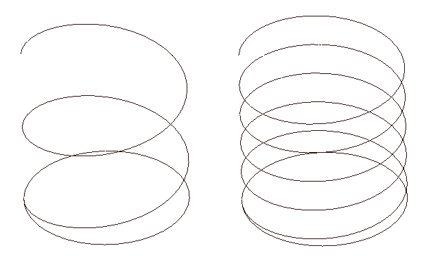
SL6-Hx   Here to be seen in the milling dialogue HPGL CI command.is used. SL2M3 transposes this into drill-milling, means the tool moves in a helical path with the 'feed X,Y' into the PCB. The feed and the steps (Number of helical paths to the drilling depth) can be entered. The feed Z arises from the fact. At the end of the Helical path to drill deep a complete circular path is milling without Z-feed.

Example in the picture:
Helix with 2 steps (left) and Helix with 5 steps (right))


Outline Milling & Tool Path Correction
A tool path correction is not present in SL2M3. This means that if I use a 2mm cutter for the outline, I have to create the outline of the Sprint-Layout 1mm (cutter radius) is greater. The reason: Since I can create as well cutouts in the board with the outline but no way for SL2M3 of distinguishing between outside and inside is, is milled on the contour path. In a cutout section within the board do I have to create smaller the radius of the cutter this.


Drill Depth Correction
Only SL6: Since the SL2M3 Knows drill diameter, depth can be entered as the actual thickness of the board. The effective depth is calculated and stored in the G-Code.

.

The effective depth is calculated from drill depth + drill diameter x 33.5% (standard 60 degree bevel = 33.33...%).


Layout Peview   Noteb: Due to the many possible screen resolutions and versions of Windows and my little experience with graphics programming I give no guarantee for correct function of the preview

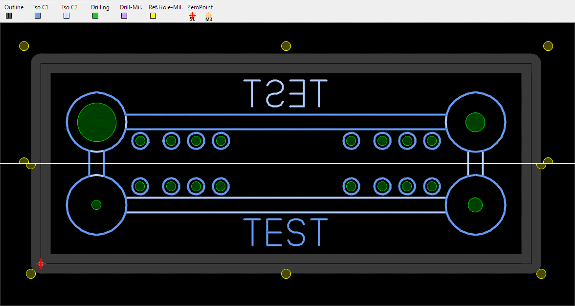
If (only SL6 milling export) completes the tool table with all missing tool diameters and a G-code file was created, reads the button [ Preview ] the created G-code again and a layout preview like Sprint-Layout is displayed.

In the preview. The colors of the individual elements are displayed in a legend about the layout.

In contrast to the traces shown in the Sprint-Layout the milling tracks in current width and the drill holes with actual diameter are shown.
If [ ⎷ M3 ] marked the preview shows thin lines similar to the toolpath screen in Mach3.

In this preview you can instantly see if any of the outline cutter collides with the pass-through pins in the holes or the width of the outlime milling cutter was too large.

In split screen pass the distance between the holes was right up to the edge of the board, set too low bottom.

Hint: If the outline created already in sprint layout of the correct width, you can already see any overlap with interconnects.


Within the dark gray cutting path is in black color the original line of the outline layer to see. The area within the dark gray toolpath shows the actual dimensions of the board.

.

The colors of the different elements can be seen in a legend about the layout.
The red zero point is from sprint layout, the orange is the tool zero point (Mach3 view).


Another possibility:

.

.

Too large (for export) value of the insulation cutter width can be recognized. There are 0.4 mm in the left Picture. The layout does not fit and must to be adjusted or a smaller milling cutter must used. On the right picture there are 0.2 mm milling cutter and is exact.

Hint: One can also see that from the previously generated contour lines when exporting in the Sprint-Layout. ( see also Sprint-Layout Help - Export - Isolation Milling - Milling width and - Create the Plotfile )


.


Operation in the Layout-Preview (View Change)

Using the plus and minus at Num Pad the preview is zoomed and the zero Key at Num Pad (if Num-Lock active) switch is back to NormalZoom.
With the arrow keys you move in the 4 directions.

The view of the board is shown from above the PCB in C1 or C2 or C1+C2, Zero point left. In (C2) the mirrored view from below the PCB, zero point right.
Only with C1+C2 both layers are visible. C1, C2, and (C2) are each only one layer and each of elements to be produced on it, including the holes.
On the opposite side of the drilling the holes can be seen as a shadow line.

With a small Button between the rulers, the background color of the preview (light/dark) can be changed.

Note: Since the layout needs to be redrawn each time the View Change, it may take a few seconds until the change is visible.This is not particularly user friendly, but met 100 percent of the purpose of the preview.


How to export the layout (Sprint-Layout)
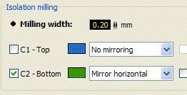
Single-sided PCBs are on layer "C2" (2nd side / bottom) are created because they allow the component side is up and everything looks correct. When exporting, then "C2" and "Mirror horizontal" Select.

SL5:
For Drilling is the easiest the same also "Bottom X-mirrored HPGL compatible".
For double-sided circuit boards must be "C1" (1 side / top) and to "top (default)" on the upper side of PCB are selected. Here as and when necessary with reference holes already to do.

SL6:
Drilling from the milling export. All operations can now be exported in one:
Reference Holes, Isolation Milling C1 and C2, Drilling, Outline Milling.

Attention:
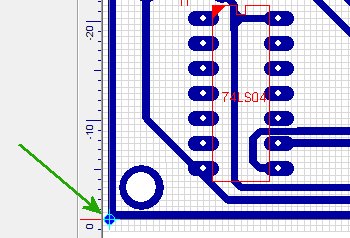
The zero point must always be bottom left according to the standard. Other positions of the zero point are not processed by SL2M3.


Sprint-Layout up to Version 5 Export - Milling:
SL2M3 converts Data from

Export -> Milling Files -> Isolation milling ->
Export -> Milling Files -> Outline Milling ->  (not shown here)

created. The resulting file has the extension

PLT

and includes HPGL-Data.


.


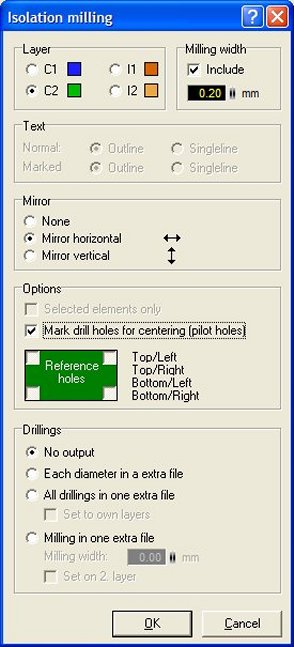
Select Milling width as required.


Select Text as required.


Important: Mirror horizontal


pilot holes protect the Drill.

Select Reference Holes as required.


With Drillings
- no Output (recommended)
   and the Drill Data Export as Excellon

or (if only one drill diameter)
- All Drillings in one extra file(not recommended!)
   creates the Drill-File DRILLING.PLT

The Option
- As Milling in one extra File (not recommended!)
   so depending on the diameter of the lands about:
   DRIL_70.PLT & DRIL_90.PLT & ...,
SL2M3 can indeed be processed individually, but not
all attach to one milling file.


Caution: To Version 5 Sprint-layout and earlier is a drilling file created here (DRIL *.PLT) differs not internally and not by the extender of a milling file. Thus SL2M3 to work correctly with the drilling files created here, the file name must include the 4 letters "DRIL". The rest of the file name before/after "DRIL" is arbitrary.

Therefore, I recommend at Drillings the option "No Output" to select, and then export the drill data as a Excellon file. Just like "real" drill data come about and the required tool changes WITH tool dimensions are included.


Hint: From Version 6 Sprint-Layout the Dialog for milling files export is visually and functionally altered (see next Page). The important options are as well available, but it can now ALL operations (Reference Holes, Isolation Milling C1 and C2, each Diameter a new Drill, Outline Milling) exported in one operation, tool changes including.

The Export of Excellon drill data (see after next page) is now unnecessary, but can still be used.


Sprint-Layout from Version 6 Export - Milling:
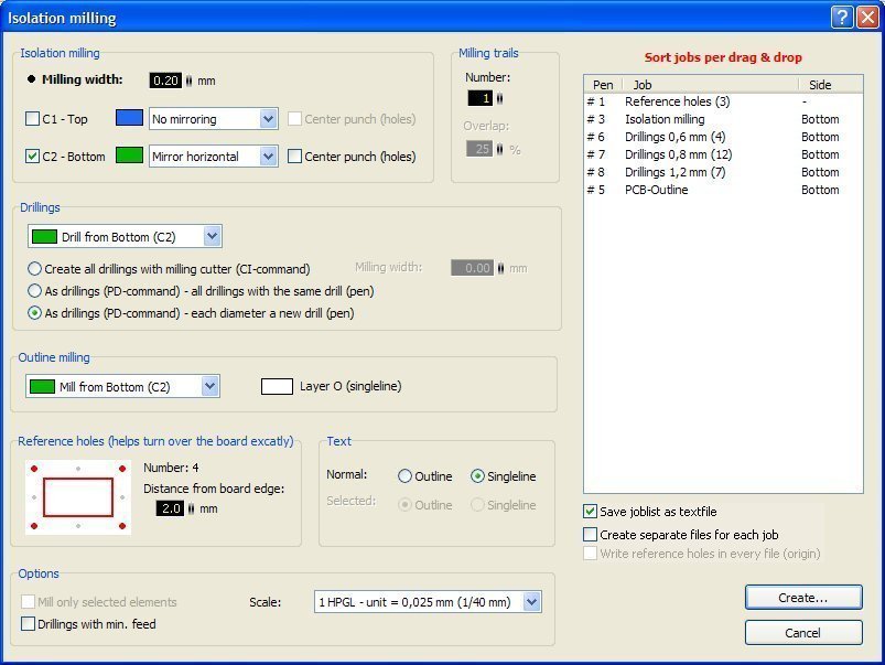
From Version 6 - Sprint-Layout the Dialog for export milling files export is visually and functionally altered.


Isolation milling:
To Milling width (and Milling trails) read the Sprint-Layout Docu
Important: C1 - Top & No Mirroring / C2 - Bottom & Mirror horizontal
Center punch (holes) protects the Drill.

Drillings:
no Output or (SL2M3 Multi-Mode*):
- Create all drillings with milling cutter (CI-command)
- As drillings (PD-command) - all drillings with the same drill (pen)
- As drillings (PD-command) - each diameter a new drill (pen)

Outline milling as required (SL2M3 Multi-Mode*)

Reference holes as required (SL2M3 Multi-Mode*)

Texte as required

.

Options:
Mill only selected elements may be used, does not affect SL2M3
Drillings with minimal Feed  NOT use (the Drill-Feed is entered in SL2M3)
Scale: the correct Format is 0,0254 mm (1mil), decide yourself but everyone
[ ⎷ save Joblist as Textfile ] must be used*
[ ⎷ Create separate File for each job ] can be used. All individual files are processed in SL2M3 in one pass.


* Caution: SL2M3 automatically tries to find out whether it has been used in SL6 milling export ONLY Isolationmilling or ONLY Drilling or Isolationmilling AND Drilling/Outline/Referenceholes (Multi-Mode, for SL2M3 recommended).

Therefore it is necessary to activate the option [ ⎷ save Joblist as Textfile ]. There is no other way a milling cutter or a drilling tool Top (K1) or Bottom (K2) to assign.

SL2M3 can handle this job list. Thereby can be output in the G-Code the Tool Changes, Drill Data in real Drill cycles be converted and...

...a tool table in the exported milling file folders stored as a file with the name  *_tooltable.txt  and can (apart from the Display tool in Mach3) be used as an aid to tool change on the machine.


Sprint-Layout Export - Drilling:
SL2M3 converts Data from

Export -> Drill data (Excellon) -> HPGL-compatible

created. The resulting file has the extension

DRL

and includes Drill-Data.

This file also contains the tool change for different sized holes (see also Automation).


.


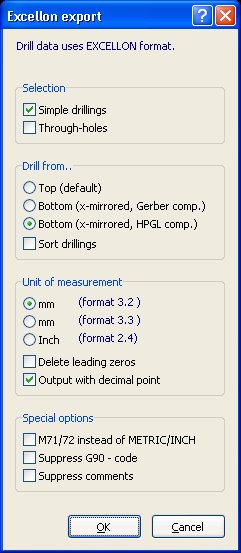
Selection

If Trough-holes used in this course are chosen.


Drill from ...

 Bottom (x-mirrored, HPGL comp.)

Sort drillings not* choose.

Unit of measurement
"mm" (format 3.2) **

Delete leading zeros may NOT be selected
Output with Decimal point see below    (in SL5 and earlier not available)

Special options

M71/M72 instead METRIC/INCH as required

Suppress G90 - Code should not be selected

Suppress comments may not be selected ...
otherwise as a result of SL2M3 only salad or nothing ****


Caution: From Version 6 Sprint-Layout, there is also under Unit of measurement the option Output with Decimal point. This option is not absolutely necessary for processing with SL2M3.
But I want to have the tool table conform to the milling export from SL6 (Drills from/up Tool Number 6), then the decimal point must be set, because SL2M3 can only find in this decimal point the difference of SL5 to SL6.
The better option is still exporting the holes along with milling data from the SL6 milling export.


* Sort Drillings is in principle no problem, but it is here that errors occur sporadically in the assignment of the drill (diameter) to the correct holes. Because so far I could not catch the problem because of the sporadic occurrence, please DO NOT use.


** The mm (format 3.3) SL2M3 can also process, but this format is actually nonsense, as due by the HPGL system the 3 Decimal place is always 0 (zero) results. Therefore, mm (format 3.2) is the attached Unit of measurement.


*** If the comments suppressed, SL2M3 no longer works because it the Excellon file is detected.
      If the G90 - Code suppressed, the coordinates are conclusive as absolute defined


Installation
No installation is necessary. Simply copy SL2M3.ZIP to the desired folder, unzip it and start SL2M3.EXE.


Bug Report
I try to consider ALL possible variations of the export of Sprint-Layout. This much audit work is necessary, and it can also "go through the cracks" something. In SL2M3 program therefore Errors also occur.
Some rare bugs that I could not verify exactly will be informed by a message box with the text "! ... Error #" is displayed. A file named SL2M3_error.TXT is created in the folder of SL2M3.
For Troubleshooting it helps me when you sent this file via email (WebMaster@B-Pahl.de) to me. (Help> Email ... menu)


If SL2M3 not work
SL2M3 works fine under Windows XP 32-bit and Windows7. In Windows64, Windows Vista, Windows87 or higher I can't test SL2M3.
At fault crashes please first see that the last Sprint-Layout Update and the Last Version of SL2M3 is installed.
Then try the compatibility mode Windows XP SP3 and possibly run as Administrator.


Update-Service
When [ ⎷ Auto Update-Check ] in the Info-Screen is enabled, the program displays a message when a new version is available. If desired, the default browser will launch and display the download website.


Version Numbers
I can with the terms version, release, and so on begin not so much. Version numbers, such as 12.123.00.002 mischief are in my eyes. With me is the version number of the year, the month and the day of publication, even if only a tiny bug has been fixed.


The law unfortunately inevitable
- SL2M3 ist Freeware, can be freely distributed and used freely.
  But Small donations are gratefully accepted, please contact (WebMaster@B-Pahl.de) (Help > eMail… Menu) or use the SL2M3 Websites Donate Button.

- SL2M3 is used at your own risk. I assume no liability for any damage to hardware or software.
  I am a hobby programmer and can not afford guarantees.

- All files of SL2M3 are summarized in a ZIP archive SL2M3.ZIP named. Please pass this archive without alteration.
  This documentation SL2M3-DOC_EN.PDF is a part of the program SL2M3, is a component of the archive.
.


SL2M3 © Bernhard Pahl
www.b-pahl.de ... SL2M3 / Isolation (PCB) Milling

Thanks for supporting goes to A. Reinert, Nick De Torfino, Sam Reeves, Frédéric Bany
and all Users of the Program, told me Bugs or have made proposals.


"Sprint-Layout" is a Program of the Company "Abacom Ingenieurgesellschaft".
http://www.abacom-online.de


"Mach3" is a Program of the Company "Artsoft".
http://www.machsupport.com


FAQ


Q: I SL2M3 entered in "Revolutions" (Spindle Speed) 11,000, but only 8,000 of Mach3 shows?

A: In the Mach3-Menu "Config > Spindel-Pulleys" 8000 is probably set as the maximum speed.
Mach3 displays: too fast for pulleys, using max.


Q: I have set in SL2M3 at "tool change height Z" 50. The tool moves on after the change 70 high
and then only down?

A: In Mach3-Menu "Config > Safe Z Setup" ist set 70 mm. I recommend in SL2M3 this in Mach3 entered
Z-Height to use.


Q: Sprint-Layout sets the coordinate origin in the upper left corner (Note: Only up to Sprint Layout 5).
But for milling or drilling but is actually the origin in the lower left corner!
When I compare the coordinates of which output from Sprint Layout have to drill into the empty,
where's my mistake?

A: No mistake. Pull the origin on the lower left corner of the PCB in Sprint-Layout before exporting.

.


Q: I export from Sprint-Layout a milling file Test-V3.x.plt. In SL2M3 I get the error message "missing job list" even though I have set the tick to export the job list in Sprint-Layout.

A: The job list from Sprint-Layout should named Test V3.x_joblist.txt, but is exported as a Test V3.x.txt. This recognizes SL2M3 not as a job list. So in the export filename remove the extra point.


Q: Why is in the layout preview the zero point moved to the right when looking at the (C2) mirror level?

A: In Sprint-Layout the levels (C1/C2) always viewed from the upper side of the board, the zero point is the bottom left. Could I see the board from below look (mirrored horizontally) would be zero at the bottom right now. That's the idea behind this presentation.


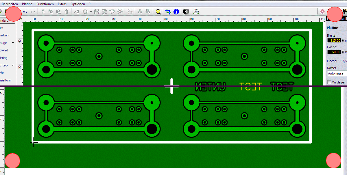
F: My Layout with active auto plane shows shifted Reference Holes after conversion with SL2M3?

A: Move your Layout in the upper left Corner, change the size of the PCB less than the size of the size within the (imagined red) Reference Holes and SL2M3 gets correct data from Sprint-Layout also with active auto plane.

.

Correctly above, wrong below.